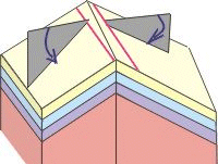

Rocks contain structures that are planar and structures that are linear. It is important to record the orientation of these features, using a COMPASS-CLINOMETER. Lines and planes are measured in different ways.
Lines (1D features in a 3D world)
A line has a direction (relative to North) - called an AZIMUTH. This is generally recorded in the direction pointing downwards. The amount the line points down (between 0 and 90º) is called the PLUNGE.
Examples of lines:
l-tectonites, fold hinge lines, lines of intersection between two planes (e.g. bedding and cleavage).
Planes (2D features in a 3D world).
 This
is recorded with a STRIKE and DIP with dip direction.
A strike is a bearing (relative to North) of an imaginary horizontal line on the plane.
The dip is the amount down hill the plane is inclined at (so has a value between 0 and 90º). The direction of dip is 90º from the strike
Notice that we also need to record an approximate direction of dip.
This information is measured for any plane - so if you're collecting data it becomes crucial to state what type of structure it is that you are measuring.
Examples of planes:
Bedding, cleavage, joint surfaces, fault planes, fold axial planes, quarry faces.
Lines on planes
Some line features exist on planes, and can be measured with reference to that plane. The measurement is called a pitch. First measure the plane. Then place a protractor flat on the plane aligned so that the base-line of the protractor is parallel to strike of the plane. The dip direction is 90º to this. Now identify the line you are trying to measure. Measure the angle this line makes from the strike of the plane using the protractor. If the line runs in the dip direction it will have a pitch of 90º. If the line runs parallel with the strike it has a pitch of 0º. So the value of pitch varies from 0 to 90º.
But consider a line pitching at 45º on a plane that strikes north-south (and dips gently eastwards). There are actually two line-directions that satisfies this description, one inclined towards the NE and one to the SE. So to remove this ambiguity we specify the direction of the strike (either north of south in our hypothetical example) from which the pitch was measured (i.e. N or S).
Examples of lines on planes
Striation or mineral fibres on fault planes, glacial striations on glacial pavements, sole marks on bedding planes, lines of intersection between two planes, l-s tectonites.